Weather | Buy&Sell | Forums |  |
Weather | Buy & Sell | Gallery | Forums | |
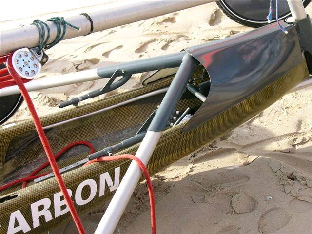
Just remembered, have this pic of a french yacht that can adjust the seat forward or back also the steering ,worth thinking about.
jeqs said...
Francoise Papon from France, sent me these plans of the Class 5 Sports.
Mr. Landyacht introduced me Christopher Roger, who was interested in spreading this plans in order to be able to have more competition in the future.
( apparently they need more class 5 sport pilots and landyachts.)
I really want to build it, but the plans are missing lots of information ( angles, measures etc.)
I am trying to figure out how to explain francoise in a mix between english, spanish and some loose french words about more details needed.
juan enrique
Side View

View from Above.

Just adding ott class5 build so that we keep a reference to post
www.seabreeze.com.au/forums/Land-Yacht-Sailing/Construction/Plans-or-specs-for-OTT-class-5-build/
Landyacht posted an English translation and details figured out.
www.seabreeze.com.au/forums/Land-Yacht-Sailing/Construction/Class-5-Sport/
Here is the drawing for my modified Fed 5 front (lots of digging through old computer files)
it had reasonable handling with this setup, which is remarkably similar in trail to my Rocket which is even more stable. The Rocket's front tube is much nearer to being aligned with the center of the wheel.
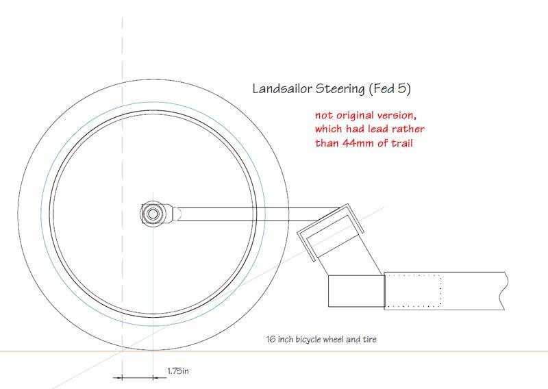
With regard the last post, the ORIGINAL drawing for the Fed 5 DID NOT have any lead nor trail. As with any good layover the axis of the steering pivot meets the tyre patch exactly. It may be that what was made has lead or trail, but as I still have a set of the original drawings which Mike Hampton did in my hand right now, I can assure you he is pedantic on this point.
If you had built as many yachts as Mike, you would know this better than you know your family!
Kiwi307,
Sorry, should have said, "The way the original US fed 5s were built" the original Mike Hampton drawings indicate zero trail as you stated. Someone did something not like the really original drawings when they built the US feds. I think they actually had lead.
More about flop over fronts: In several other threads I have seen forks with very low pivot points. Does that give more steering and less flop or is there another reason?
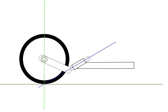
the drawing youve shown is what we use on our minis as it is easy to attach close up solidly attachedfoot or hand steering. i would have to credit the idea to paul Becket of Blokart as his was the first i had seen , although Ive now seen similar set ups that occured at the same time.
My own thinking is its not that good a set up to attach class5 5 type steeering shafts or cables, but it is really great on the minis where the feet come closer than 300mm or so
Another question; What spread angle is the best for the rear axles?
Anywhere from a straight axle to axles attached to the mast base would work, and 'straighter = stiffer' I'm sure, but how much flex is good?
Would it be better to have a straight/rigid axle for hard pan/salt bed, and flexy flier for rougher ground? The longer angled axles would allow more 'suspension', but would also cause a loss of power due to the flexing. Might be a real handfull to control in a gusty/rough ground situation even.
Landyacht brought up this question in an old post i can no longer locate, and I'm not too sure what the answer was.
I want to build another class 5 type yacht, and am getting more confused by the minute, looking at all the options including the wheel sizes, frame over/under, angle of the 'Y', etc.......
There, that shouldn't muddy the waters at all, huh?!?! ![]() [}:)]
[}:)]
My understanding of flexible axles is they store power in the peaks and release it
in the lulls The rules of class 5 metal tube axles was the reason axles became longer
and angled to get the flex
Some other classes have more matierial freedom
There are people on this forum who have been with landyachting long enough to be able to give the answers on this and other design evolvement with the class5
Some earlier posts have covered these topics as well
Could it be more along the lines of lowering sail area in the gusts (heeling moment), and increasing sail area in the lulls as it rights itself?
That would make sense to me ![]()
Big can of worms...
Storing and releasing energy: yup, that happens for sure. The catch is what gets absorbed from potential lift or move you-forward-energy doesn't necessarily get released as the same kind of force, or in the right direction; it is not always like winding up a spring. If there is any dampening in any of the materials doing the flexing at least part of the energy goes to heat and noise and material degradation and???? Aluminum makes a lousy spring.
On the other hand, There are a lot of other benefits from suspension. Like not beating the pilot to a pulp. Not upsetting the sail shape, giving us some chance of keeping the boat going the way we are pointing it... And, Class 5 landsailers are often right on or over the edge of being overpowered so dumping some wind energy back into the world unused is a good thing if more power just means going sideways or blowing over. Sometimes it gets stored, like the acceleration as you come down from almost tipping over with the thing still sheeted in; sometimes it is just lost to the world like all the bouncing trying to ride a full suspension mountain bike on the street.
I find my self wishing I could go back to school and get an engineering degree then to my local trade school to really learn to weld, then someplace to learn composite molding, then apprentice with a sailmaker for a few years...Then I need to retire so I have time to clean out the garage and build something outside of my head.
The way I was thinking of the energy being stored and released was in the puffs
the yacht heels due to the pressure of the wind on the sail
In the lulls the yacht is righting itself again and the sail is pushing back against the wind to a certain extent This is how the power is stored in the axle and transferred back to forward motion "Every action has a reaction"
The pressure and flow is therefore more constant and smooth and not disrupted by the shaking of the rig and when a wheel lands back down hard from a rigid chassis
Just a theory that seems to make sense to me but my thinking has often been changed in the past no doubt will be again in the future ![]()
This is why I love this Forum. We have a bunch of (Essentially) Blokes with a common interest that are prepared to look outside the box. People that are using their heads for other things besides bashing Nails in.Great Stuff! As you guys know I am only a New-by to LY Sailing and Building.
Axle Flex and Energy Storage et Release.
My build as those who have read my thread will know I have used a lot of Old Damaged Carbon Fiber Masts, some of which have failed in their particular use or lack of Engineering though, both in the Schrodinger's Cat and Occum's Razor.
However to date the Axles have survived nicely, both in the Razor and the Cat. In the "Y" Frame situation there is a lot of spring activity to the point the Razor just about lulls you to sleep "Rock-a-By-Baby in the Land Yacht"![]()
![]()
![]() That's Cool!
That's Cool!![]()
There seems to be very little Layover against those Axles in 10-15Kts... Go to
www.seabreeze.com.au/forums/Land-Yacht-Sailing/Construction/Just-working-out-a-build/?page=11
The Pic's there show a great deal of energy usage I feel.
However if one takes the Axles (No Pic's available) on the Cat "T" Frame, she becomes a real Bone Shaker on Rippled Sand even on the Tarmac you could hear and feel the surface. The axle length between the 2 machines vary around 170mm in length and are approximately the same in other properties including rear wheel spread.
Both machines GO like the Clappers when quartering the wind and sail very high to the wing the Razor seems to accelerate or at least held as close as 5degrees from directly upwind, the Cat would be very close to that as well. I was shocked to think that these beasts could come up so close-------------------------, At least in my inexperienced hands. When sailing directly down wind the sails went slack very quickly as we gained wind speed.
From observation I did note the Mast laid over under Gusts but did not take the yacht with it. At no time Did the Razor Lift a Wheel under Gusting Wind, however in slightly lighter conditions the Cat did lift a wheel, several times under gusts. In the case of both machines the Steering appeared to improve vastly with speed and wind speed (Probably normal for all machines)
I just thought I'd add a little fuel to this Debate[}:)][}:)]Sh**t*!
Ron
I dont have a problem with that concept it would bounce forward on an arc of radius
equal to the wheelbase 2.5M I would imagine
Assuming the front wheel doesnt bounce also
Much the same principle that a child moves forward on a Pogo stick
[ I havent seen one of those for years!! ]
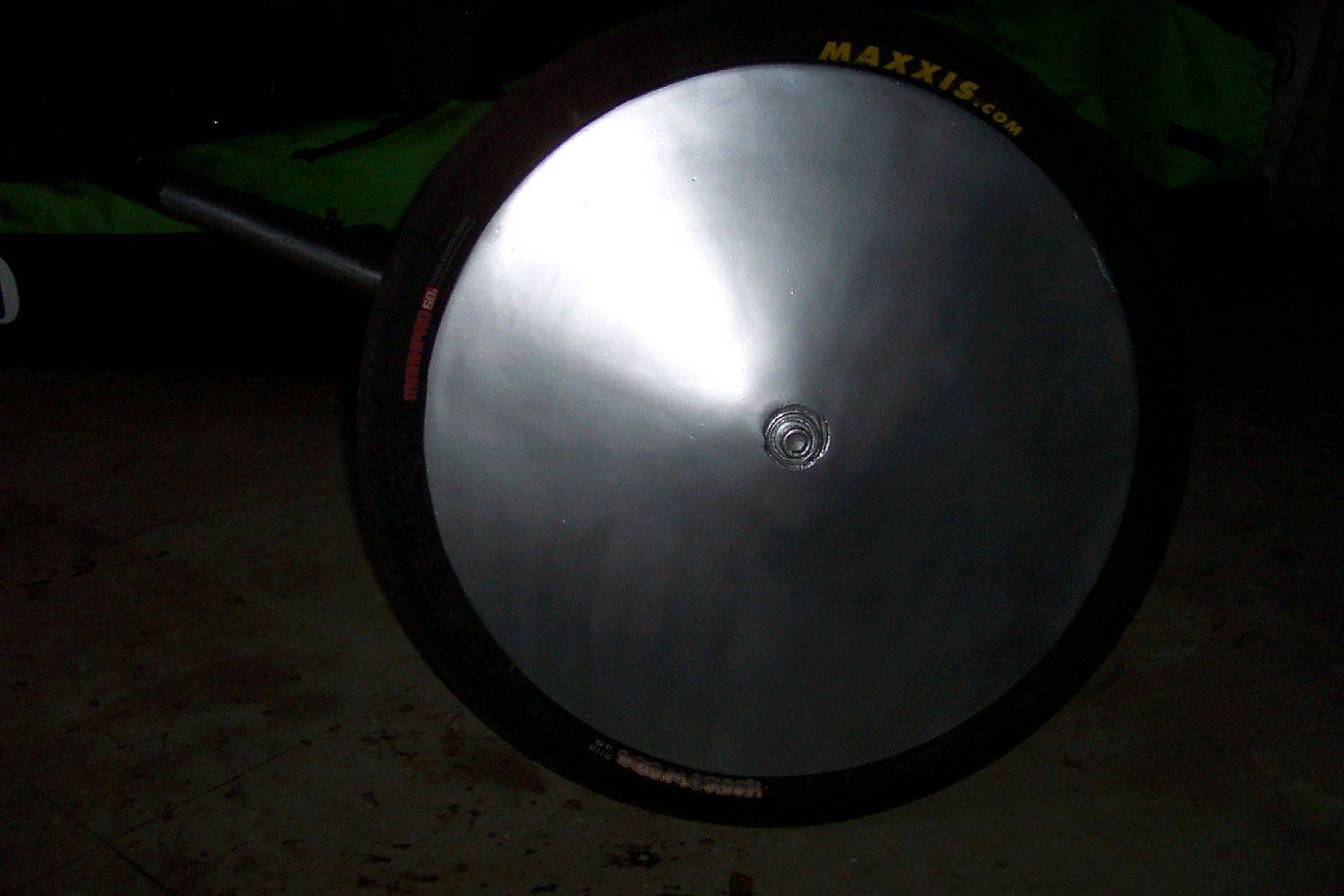
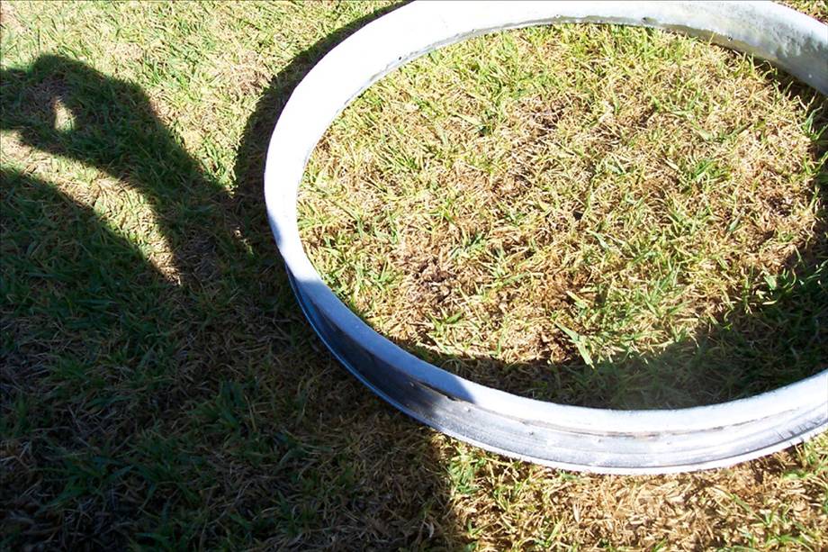
I have had a few PM over the time on how did I go about making aus230 26" wheels. Finally got to where I think I am happy with the final wheel. So here goes, feel free to pm on any part of the build.
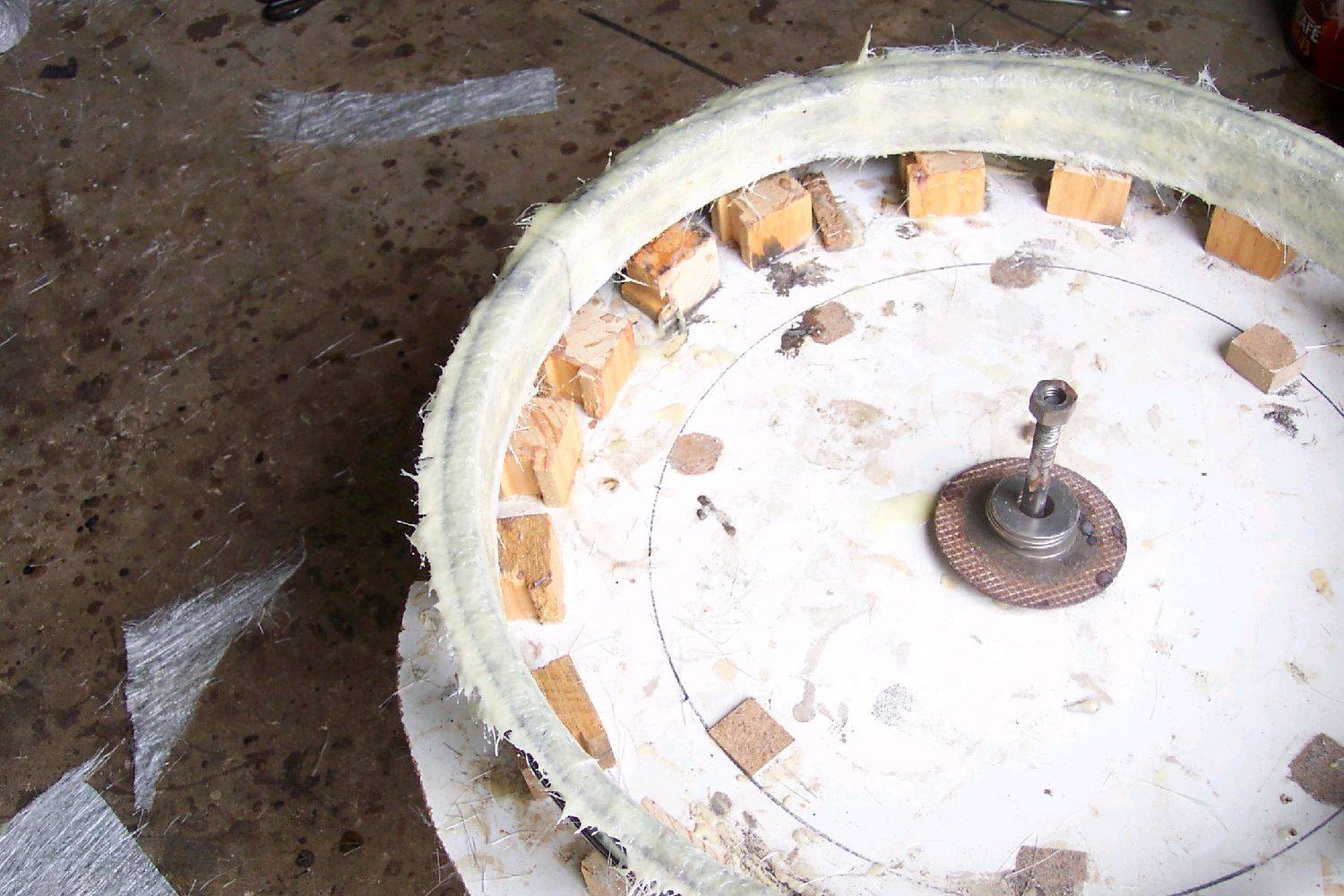
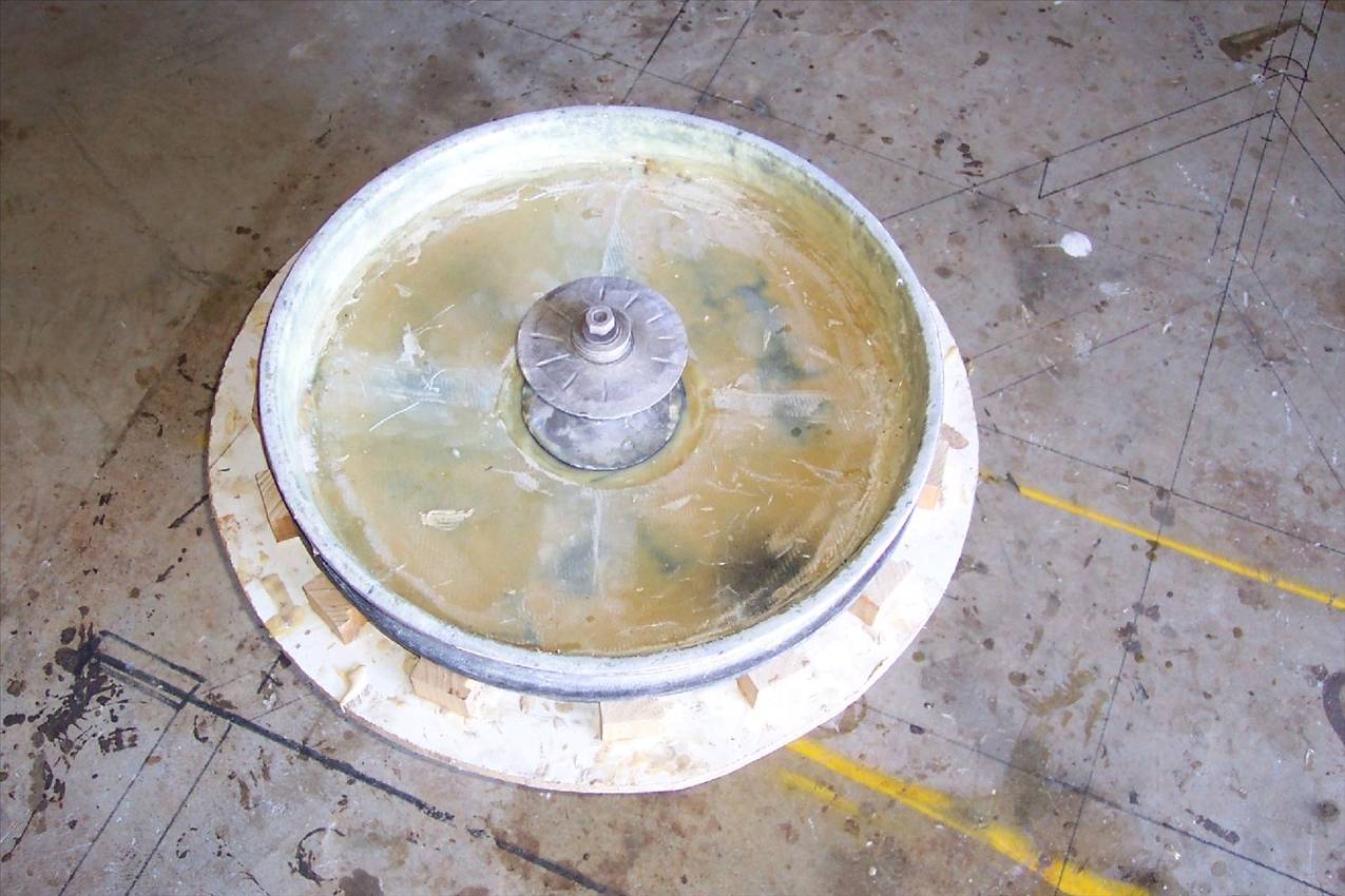
To make the plug I used a 26" mountain wheel, Covered the spokes and then filled in with molding using the out side and center of the rim for a guide, sanded soothe.
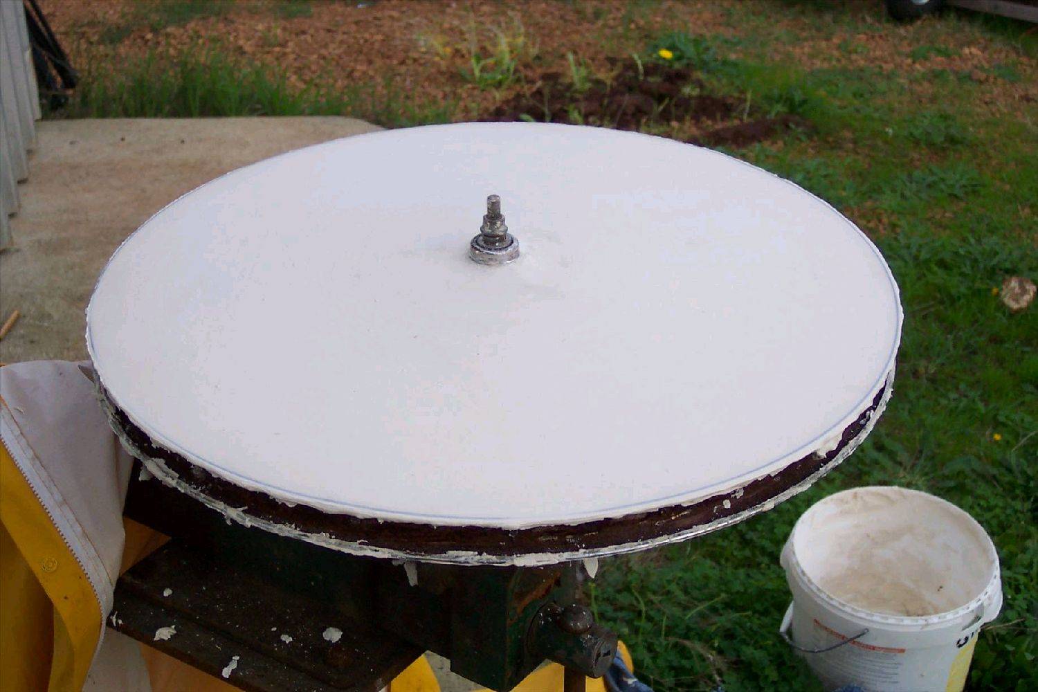
Sealed the plug with shellac,several coats of mold release wax them sprayed on mold release
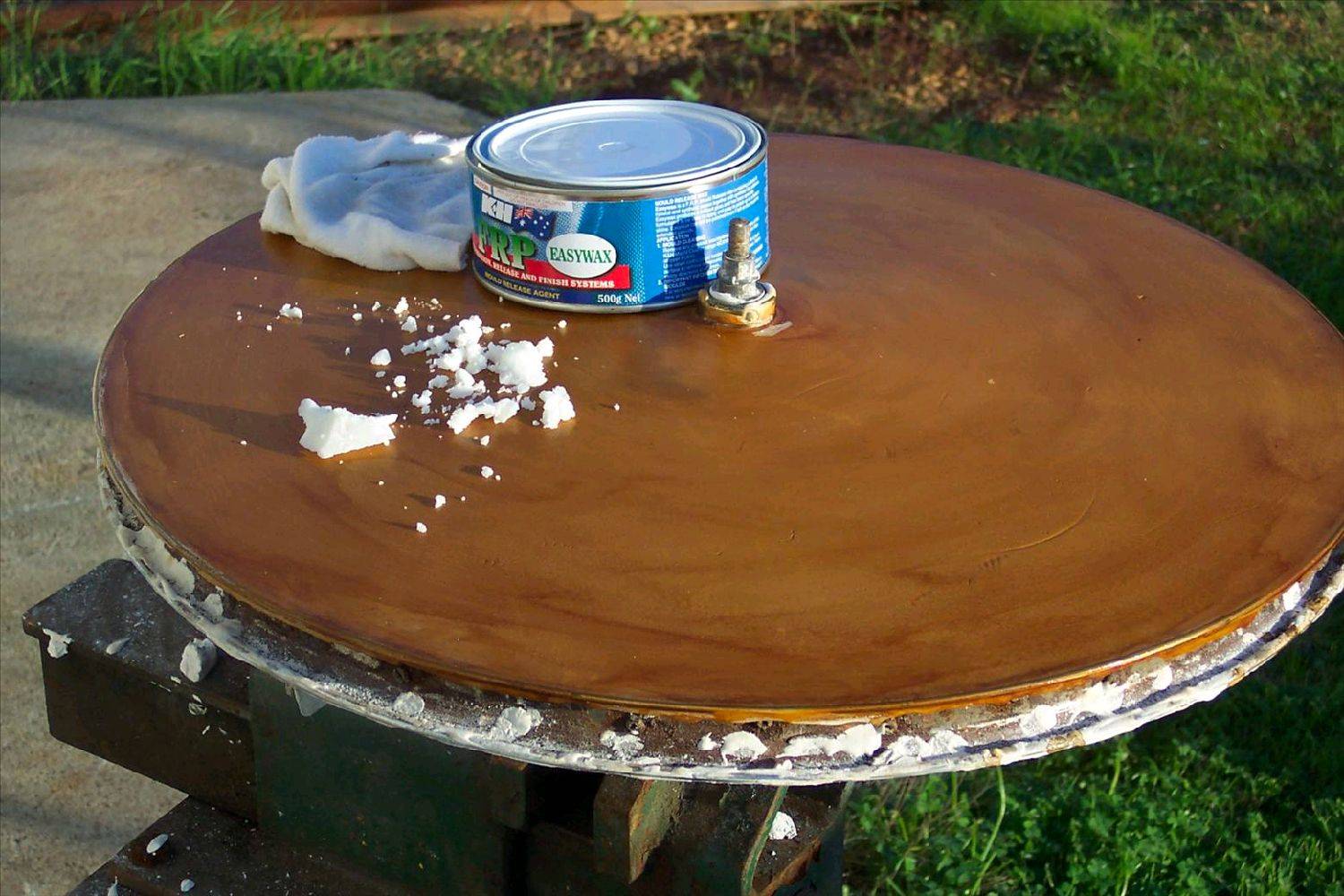
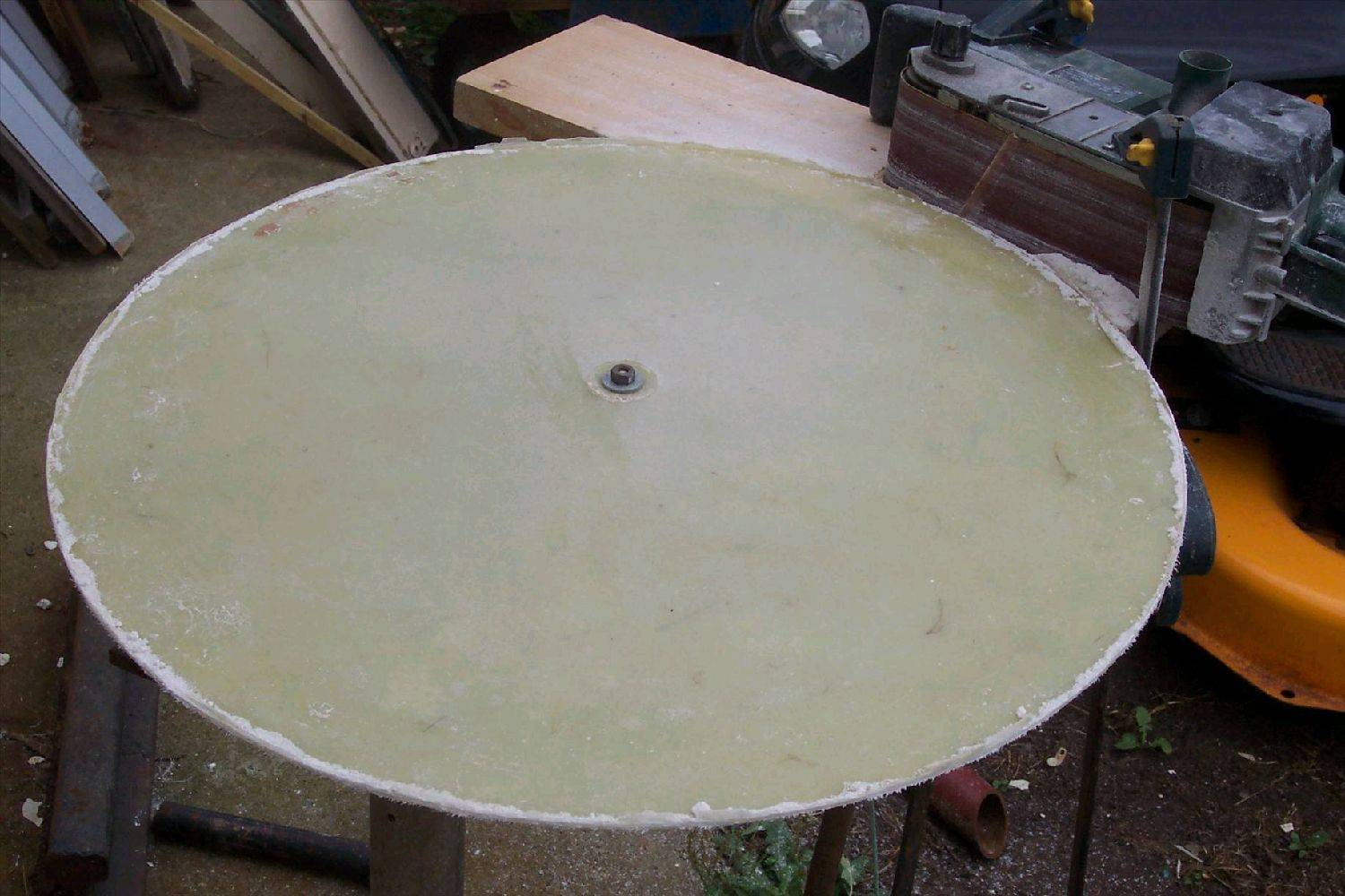
Layed up several layers of fiberglass mat over plug to make the mold

Sealed the mould with shellac,wax.spray on mold release to make dics. Made up a gig using a fixed sander to true up the dics.
Dics 2x 8oz woven,2x 4oz chopped mat, Epoxy resin required for construction.
Two steel mountain bike rims required to make one wheel
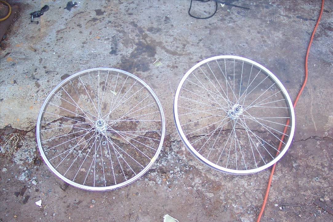
Cut the outside enge of one side of each wheel (after removing spokes)
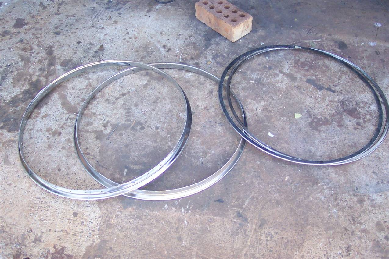
Weld rims together
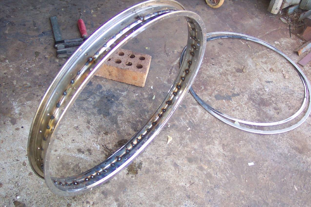
Cover inside of the rim with fiberglass
Fit rim and hub to dics (gig required to hold everything square)
I have now used 8 light spokes insted of 4 due to the rough surface that we race on
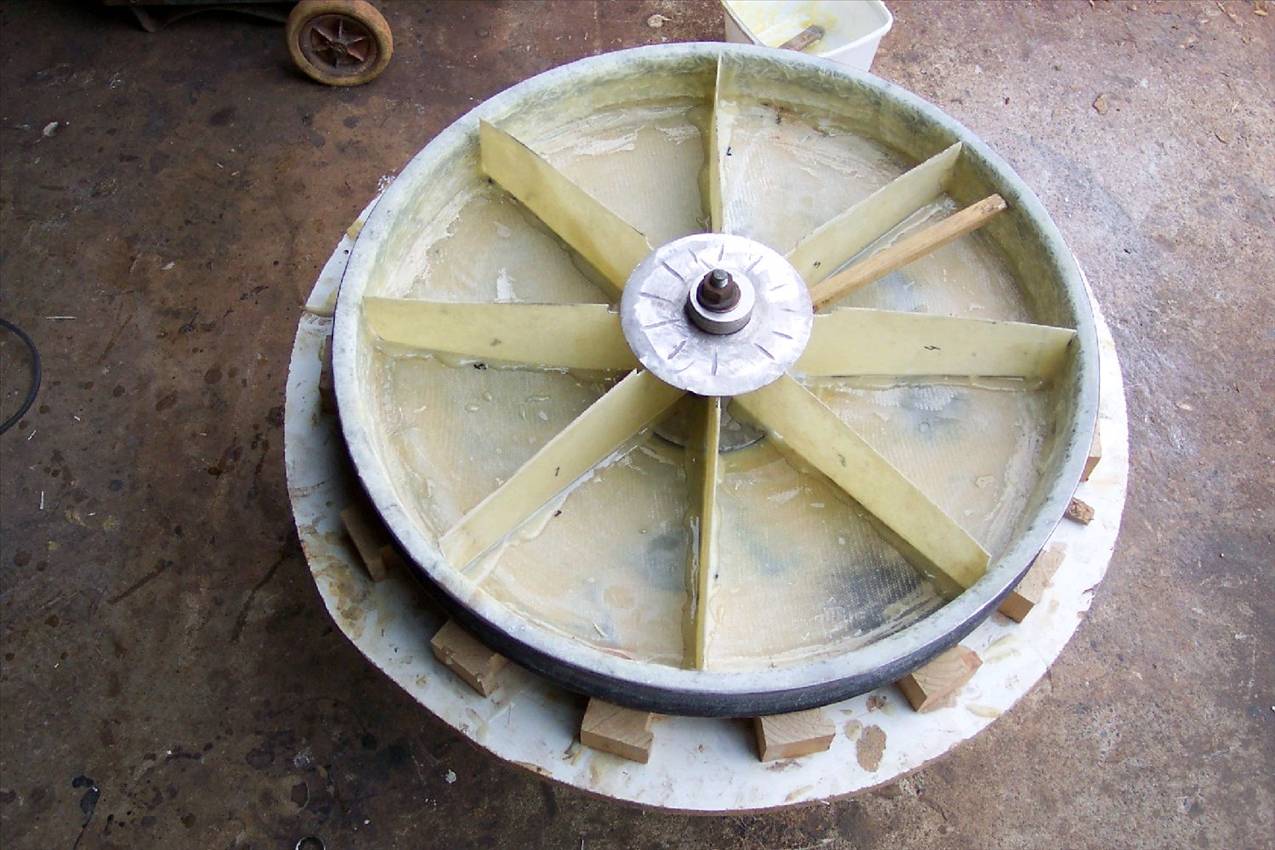
Add 2nd dic and run a 2" fiberglass tape on the tube side of the rim.
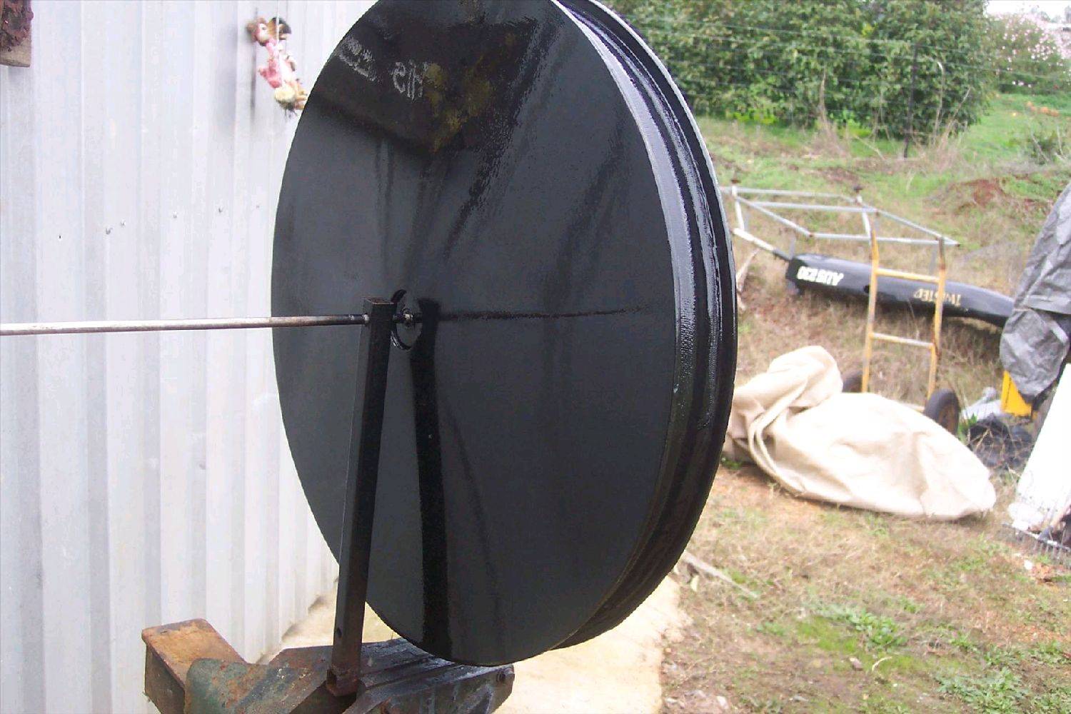
Hube's will have to be turned up to suit the type of bearings used, I have used the hubs from some old plastic wheels that I wrecked.
Hope this gives a general idea of how to go about making a set of wheels that will not break the bank
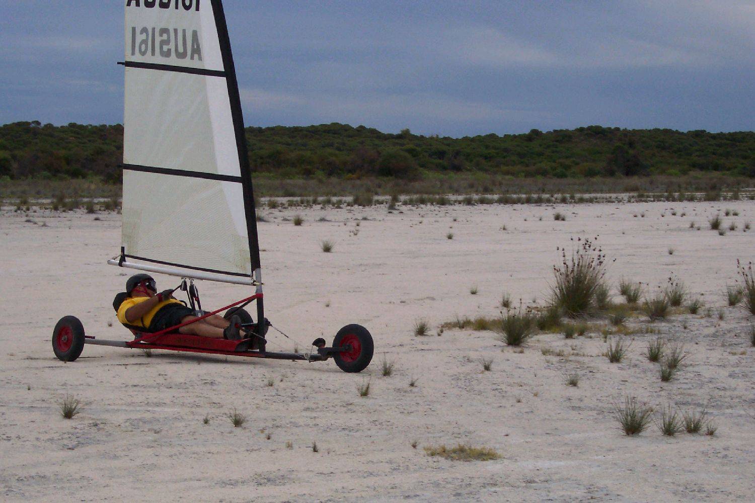
aus230 with wheels
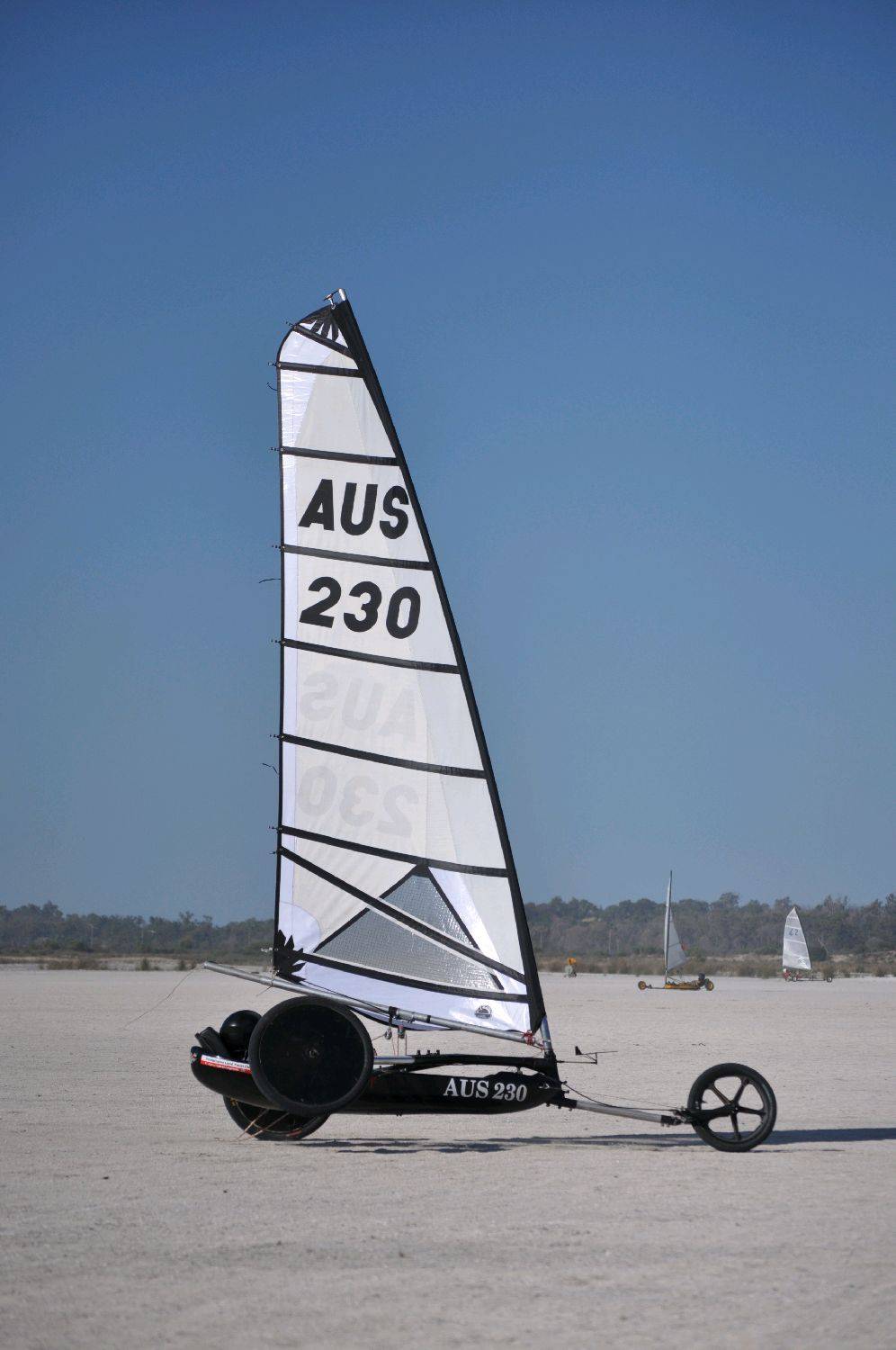
Cheers
aus230
Vic,
Thanks for the details! You have answered a lot of my questions. Not sure if you've encouraged me to to try building wheels or convinced me not to. Are the disks are just bonded to the edge of the rim, no glass wraps around into the bead? How wide does the rim end up being?
Thanks again, great info.
Blake
Hi
the outside of the rims are encased in fiberglass before adding dic and spokes. The rim is bonded but I guess we could say it sits inside a fiberglass rim so it is very strong. I tape the outside of the rim(tube area) ,but not the bead.
The rim ends up 2"wide and takes 2.5 maxxis hookworm tires
Cheers
aus230
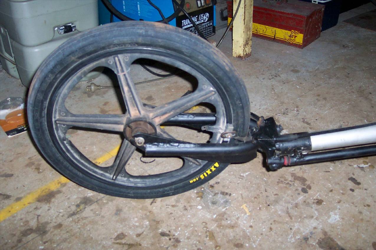
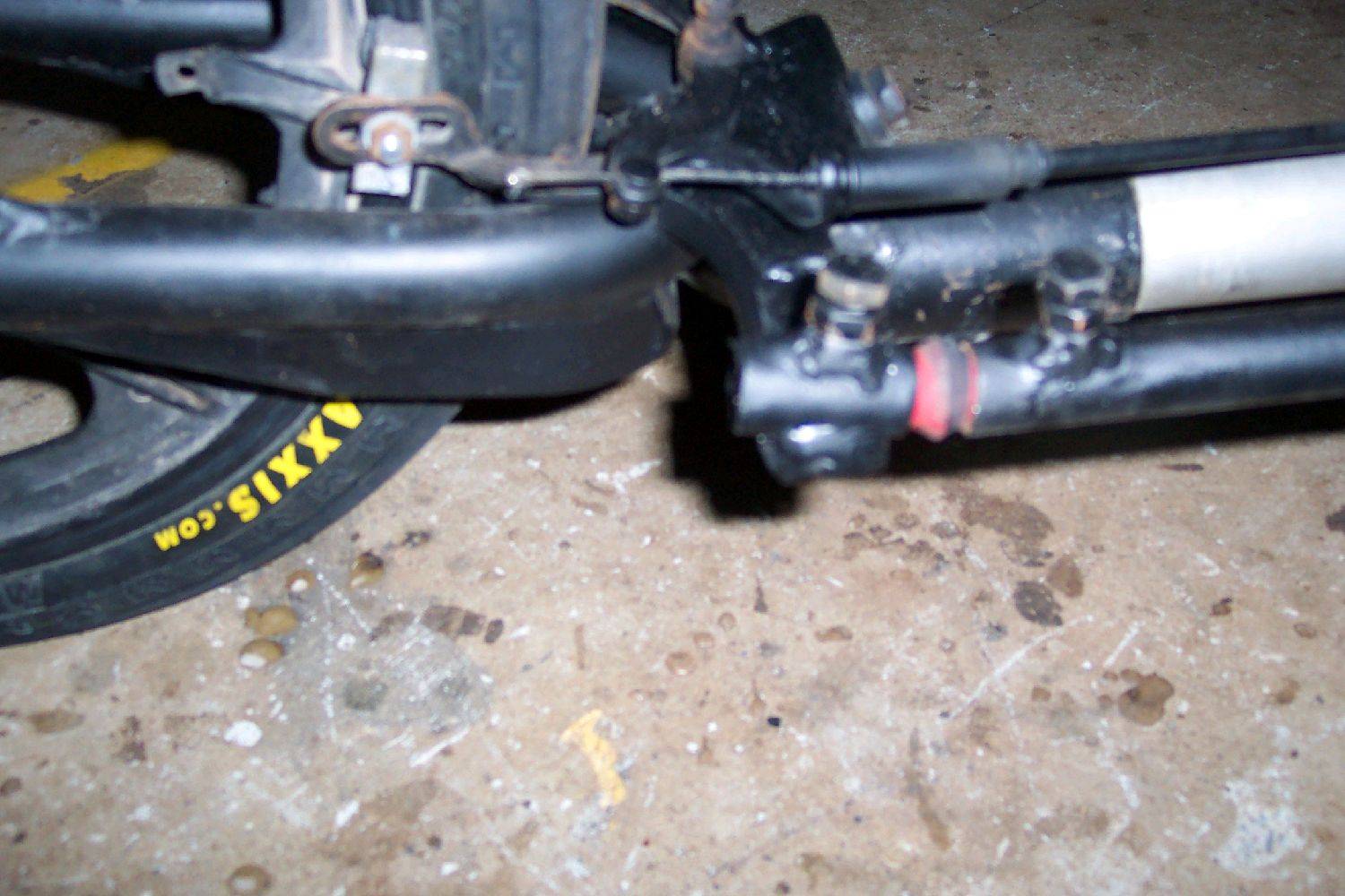
I have just changed aus230 to a rod steering system, I have used a flexible Nolathane rod joiner, I am a bit nervous about this system, has anyone had any problems with the material and does it fatigue over time.
cheers
aus230
I have just changed aus230 to a rod steering system, I have used a flexible Nolathane rod joiner, I am a bit nervous about this system, has anyone had any problems with the material and does it fatigue over time.
cheers
aus230
We used them on our Fed5's for years and never had a problem. Main thing is to pre-drill the hole that the pining bolt goes into. Dont just force it into the material.