
Hi all
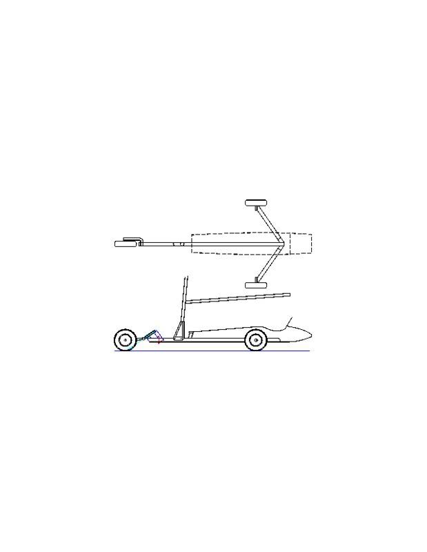
Here is the drawing of my L/Y with the swept forward axles. The drawing is to scale, sorry about all the empty space, I dont know how to remove it (yet). The yacht has a wheel base of 2400mm and the overal width across the wheels is 1600mm. The axles are 800mm in length and the line shown near the junction of the axle to spine is where the axle will join to the main chassis, ie. the point of attachment. The axles are connected to the spine by a single internal bolt assembly specificly designed for the job. The fairing behind the seat can be deleted or left in place. If deleted, the body would end at the backrest. The swept forward axles certainly provide lots of suport for the body/seat section. The extra support for the seat/body will allow a lighter unit to be made. The shape of the body is perfect to reproduce as a fiberglass form, fully shaped with compound curves for strength, lightness and streamlining. With a few more hours of work, I could add leaf spring suspension. I would prefer torsion bars but they are lots more work. Your comments are invited and appreciated.
Kody
Heres a cropped version of your diagram, I didn't change a thing in the design just deleted the space in Paint.

The design looks good to me. Not that i know much about LY design but from what I can see it looks good. I definately support the unconventional aspects ![]()
May i ask how dedicated suspension, like the mentioned leaf system, would be incorporated?
EDIT: if you want to replace your image i'll delete the one in my post just to neaten up the thread.
Hi Lachlan,
Thanks for the offer about changing the large drawing. However, I am unable to edit the post. How did you do the cropping in Paint? It certainly makes a neater job.
I am working on a design for a leafspring that is fastened to a shortened axle and the wheel is fastened to the end of the cantilevered spring. The spring will have to be custom made by a spring manufacturer. I am fortunate to have one of Australias largest spring works here in Rockhampton about 35klms from Yeppoon where I live. The difficult part will be to work out the length and thickness of the spring. ![]() This is where the spring works will be able to help out. I used to work there doing maintenance and CAD drawing.
This is where the spring works will be able to help out. I used to work there doing maintenance and CAD drawing. ![]()
![]() They (Dobinsons Springs and Suspension 07 49277 444) certainly know what they are doing when it comes to springs. I would like to use only one leaf but I suspect that two leaves may be the go.
They (Dobinsons Springs and Suspension 07 49277 444) certainly know what they are doing when it comes to springs. I would like to use only one leaf but I suspect that two leaves may be the go. ![]()
It would be realy great if an "off the shelf" spring could be adapted, like a slipper spring for a boat trailer, but the hard part is drilling the required holes in the spring itself. Also, the leaf will have to fit a particular curve to enable the best performance to be obtained. I can understand how rough it would be on the tender parts of one's body to "cruise" around a rough and bumpy paddock with only "tyre" suspension. When I finalize the design, I will let you all know the fine details.![]()
Kody
To crop the image
- I simply dragged a box around the desired item ('box' icon is at the top left of the tools menu in my version).
-cut it out (ctrl+X)
-opened a new canvas and set the canvas size to 5 by 5 (exact size is not important)
-paste the previously cut image there and say 'yes' to the prompt asking to increase canvas size.
-save the image as a JPEG, GIF, or other format you like and your done.
Hope that helps you out. As for the suspension notes Im always very interested to hear about developments. I see the use of car wheels is limiting my crafts performance to a degree (I guess) via the mass increase. I haven't looked seriously at suspension as the mechanisms required for it are heavier than the car wheels because Im limited to working with steel, or too complex/expensive/experimental/etc.
I'll be keeping an eye out here waiting for more on this build. How close do you think you are the some metal morphing?
with the axles coming out from under your head you will feel evry bump you go over, thats one of the reasons we started to sweep the axles forward. Check the cl 5 specs in the articles section regards suspension
Here is another variation for front suspension (Bill Finch Design).
A long length of bungee cord wrapped around the main spine and front end.

Hi Lachlan
These are basic drawings of an idea. The first drawing shows the layout of a leaf spring fastened to each end of the rear axle. The spring might be a single leaf or might use two leaves. It is bolted to the main axle (50x50 RHS) with two 10mm Grade 8 bolts. The axle for the wheel is threaded and bolted to the spring. The axle is machined with a flange (not shown, error) to position it in the spring. The leaf extends aprox. 350mm past the main axle beam. This length should give the required flexure.
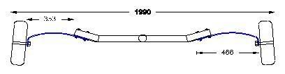
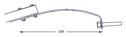
This drawing shows more detail of the spring. The horizontal distance, 465mm is shown and is not the actual true length of the spring. The spring material as a guesstimate would be 50mm x 6mm in crossection size
The front wheel spring would consist of two leaves, 32mm x 6mm bolted each side of the wheel. A basic (read: rough) guide would be to attach the axle with two "U" bolts or make a specific clamp to suit. The rear ends are bolted to a cross bar or RHS section. The two leaves are curved to give more uniform flexing. This spring assembly would take a "fair hiding" as it's at the front and I feel the extra length is necessary.
These drawings are nothing more than IDEARS. If you like what is shown, I recomend that you take the drawings to a competent spring maker and ask for more specific details re. final shape, material width and thickness, number of leaves and especialy, the cost of the springs. The front spring might be able to be made from two 12mm diameter bars or perhaps 14mm dia.
If nothing else, the drawings and idears will give you something to make a start with and you might even modify and reshape them to something entirely different. I hope it's a good start for you. I would have a go at it myself.
regards,
Kody
Hey all.
Do you think the problem landyacht highlighted could be solved by mounting the seat on a cussioned mount, say a rubber object that soaks up some of the bumps? It works for cars.
I must say the front suspension looks impressively elegant, i like the use of curves. One problem though may be the keeping of wheel allignment as the suspension is worked under spring bias, as in a corner. A very stiff axle/spring union may help reduce this, I dont know. Someone else may have an idea too.
The rear suspension is elegant also although i see a (potential?) problem. As pressure is applied to the rig it will be loading the leeward (?? the downwind side) spring much more than the windward spring leading to an unlevel ride, not that this should cause too much of a practical problem if the pilot doesn't mind.
More of a problem is the suspension rates under load. I'll try to explain with an example. Here goes ![]() .
.
As a landyacht sails and turns through 360 degrees to the wind at various times we have to assume the rear springs have the same properties. The windward spring we will say is sprung so that its wheel is working with optimum suspension characteristics. This however means the leeward spring will most likely be fully compressed (my brain judgement/guestimation) as it is under pressure from the rig.
Just for interests sake I was thinking of using a similar system (though more like a swing arm setup using coil springs i.e. motorbike shocks) and attach the mast stays to an appropriate point of the swing arm. The springs are sprung so that suspension is provided to the leeward wheel under rig load (i.e. sailing with rig pressure on the leeward wheel), there is no tension on the stay under these conditions (there maybe but thats explained later). The windward wheel also has correct suspension character because the overload is cancelled out by the tension force provided by the stay (which is proportional to the pressure applied by the rig). There may also be spring loaded stays to provide more proportionate suspension activity, to the leeward wheel in particular.
Have I lost everyone? I'll try to get a pic up to show graphically what I mean in case my post is as clear as mud.
Ok. Here's what I was leaning towards. You culd of course use leaf springs, I was just thinking coils beacause they are adjustable and available to an extent.

Evening all,
Kody, you posed the question of drilling through steel spring material.
I am assuming you mean the difficulty drilling posed by the nature of the steel when using standard HSS drill bits?
A "Cobalt" drill bit run normally or a little slower with coolant/oil will very nicely drill holes in spring steel, bisalloy and other similar products, that have been or are hardened or have work hardening properties (stainless steel, bisalloy etc. etc.)
Many years ago in the town where I live (and before I was born or was very young) a fellow had a LY, the entire rear beam of which was a single very large leaf spring. This craft was apparently huge, around 20 feet long or more, and width in proportion.
I believe Gizmo knows of this craft and its owner.
Lachie, as you, I have toyed with the idea of a suspension LY because of rough paddock ground. Systems I have drawn are based around what you may find on an open wheeler race car, pushrod bellcrank. Damper unit laying down and longitudinal, another with damper laying down parallel to rear T axle, a thing similar to Kody's using mounted leaf at each end and a design using torsion bars (ala Chrysler, Valiant)
Somewhere on the net there is a grainy photo of a bloke in a LY with rear suspension, where the (coil over) spring damper units are mounted at an angle around 45 degrees.
I have completed an amount of research re coil over units, availability, cost, what/not to use etc. If you go down this path I may be able to save you some time with info later on.
My drawings have not been committed to CAD, they are all pencil and paper (beer coaster) at present
now you are all starting to think!
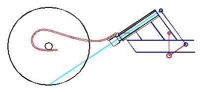
if you are going down the tubular chassis style of yacht,have a think aboutsome race proven systems like this french front end.

the suspension compresses under load and stiffens the yacht ,giving you control. ou could adapt this to the rear end ,if you wanted
Thats the seat suspension system i thought of, they stole my idea ![]() Go the rubber blocky bit!
Go the rubber blocky bit!
Landyacht! Why do you always make us look like bits of twits. I guess we are simply using springs in stead of rubber blocks ![]()
Heres a couple of photos Ive found on my web travels.


Yeah, this is great!! With this shared knowledge and experience I can see Australia being the world leader in landyacht technology in the not too distant future. Keep up the great work!! ![]()
My only concern with the rear leaf springs in Kody's design is I think you'd need something to stop them from twisting under load due to the flex in the spring, thus causing the alignment of your rear wheels to go out.
Hi ya Phil,
yeah, generally with any swing arm/suspension used in this vein (90 deg to general direction of craft travel), it requires that you triangulate or box the system (control arms) to give location control to the hub/wheel assembly.
should have said 'from forward ' sorry
Perhaps the art is in making the susspension AND cutting the weight.
Possibly, suspension systems would be most suited to hybrid LY or larger classes with more sail area/wings when "racing". Unless using anything but very exotic materials, a Class V (min 50kg, 5.5m sail) or similar performance craft, when raced in class, would possibly be uncompetitive with the increased mass. The class rules also regulate material type used in construction.
By hybrid I mean, say a Class V chassis with suspension and slightly larger sail (overcome inc. mass) for paddock or non racing.
It goes with out saying, there will always be a weight penalty when adding systems for comfort and/or performance. As Paul stated the trick is design with maximum strength and minimal weight.
Lachie, another thing I drew up was a system akin to the early Mini, that being basically, a rubber ball/solid sphere into a cone.
From what I read in the articles on your other post Kody the stays had nothing to do with any injuries. Though yes, a Vampire dragging a cable through people is going to be a problem, Im guessing it wasn't 3mm dia either ![]() . There was a myth busters episode showing the destructive power of a heavy cable at velocity. Stays may raise the danger level a little but from what I can judge the rear beam/axle is going to do the vast amount of damage. I've found they are much easier to rig up regarding construction (oddly angled metal to metal junctions [}:)]). Just food for thought.
. There was a myth busters episode showing the destructive power of a heavy cable at velocity. Stays may raise the danger level a little but from what I can judge the rear beam/axle is going to do the vast amount of damage. I've found they are much easier to rig up regarding construction (oddly angled metal to metal junctions [}:)]). Just food for thought.
Thanks for the tips Sandflyer. I've never seen a mini's suspension system although I have seen rubbed/synthetic airbags used instead of springs in racing vehicles. I've got a mini car manual in the bookshelf I'll have to have a look at. Probably wont be addding suspension to my next landyacht, it will have a removable rear axle/beam though allowing for future experimentation. At present though I think coil units are too expensive and heavy for me, if I am considering them though Ill make sure to ask for advice ![]() I reckon others here would also be interested in your research were you to post it (although id understand your reluctance to give away top secret knowledge
I reckon others here would also be interested in your research were you to post it (although id understand your reluctance to give away top secret knowledge ![]() ).
).
Doesn't anyone think the uneven pressures on the rear wheels will pose any problem?

Mind you that on their site they are claiming only 70 kmh with their machines on bitumen.
Me thinks that K.I.S.S. ends up being better than sexy.![]()
No secrets Lachie,
might just be a bit wordy if no one is going to use directly.
In a nutshell, MTB units too expensive, if use cheap versions, are exactly that, cheap, damper does not work only spring. Pit and other mini bike units in same vein.
Motor cycle units available from (new) $160/pair, 285mm eye/eye. Also available at wreckers. Adjust for bump and rebound in damper, adjust spring stiffness (wind nut up/down). "Industrial Springs" (SA) will supply replacement springs at VERY reasonable cost. Depending on terrain, craft and crew weight, you may find you need an 600lb, 1000lb or 1500lb spring etc.. Will make spring to your specs. That is, poundage, rate (single, variable), length etc. etc.
Mass of m/cycle units is only a few kilos/pair. As you construct mostly with steel and for rough terrain (strength) this may not be too restrictive.
Hey Cisco, that image of the Scirocco is better than the grainy one I mentioned. How heavy would that craft be? How much sail area? And with your super size me 125+ kilo Yank on board, you possibly could not run that thing anywhere but on hard made surfaces.
Kody you may be a big fellow here, but stateside you are an average man.
remember that the whole reason for thelong unsupported round tubes is to create suspension. If you are going to have wire stays it is easier to have a wooden back axle that is a spring. look up some photos of class 3 yachts under sail. All those old US yachts eventually went to wooden rear axles.
That sirrocco has an awful lot of bulky bling IMHO
You've both got that right. On the Sirocco site the specs of that machine were well over 50 kg.
It is definitely a different breed from the Aussie class 5 greyhound.
A bit like comparing a Chevvy Belle Aire to an FX Holden.![]()
I'm glad that people are finding good photos o these yachts for us to compare ideas. some of this stuff is making a BLOKART look very modern, and LEFROY MINI positively futuristic.


