
Hi everyone
I was wondering if there is a thread on the design and construction of steering mechanisms. The LLM system is clear to me as are some similar ones. However, on the "Madhatten Project" we intend to place the control systems well behind the front wheel and passenger. Some have suggested we use spectra lines......we need to explore all possibilities before we commit ourselves...(to the looney bin!![]()
![]() )
)
Lots of simple diagrams and pics would really help!
Hey Fub's,
When are you coming up this way. Pegg's is brilliant at the moment though it may be just a little hard on Bike Wheels in the Rear.
Ron
Hi Ron
I've just finally got around to reading all of your thread, "just working out a build".
You have obviously explored lots of the steering configurations some of which may have a suitable application for our little experiment. I've nearly decided on a system that is a bit like your quadrant concept....need to consider where to place the pulley systems etc. I've set up a dummy run in the shed with bits of wood and string etc. Any chance of you posting some more explicit, (I do love that word![}:)][}:)])diagram and or photos?
I'll post a few of the build soon.....probably on the Madhatten thread.....the troops would like to do that I think.
We are back at school now so don't know when and if we will get to the Northwest end. Would love to do so though![]()
![]()
See you were into hang gliding as a youngster!!!!.....I've still got my old "Albatross" in original condition in the shed. A long story to share sometime.....might be getting into powered hang gliding soon. Have a friend who is a collecter of hang gliders....has around 20....We have discussed using condemmed spars as masts for our project.
Happy days!![]()
![]()
Damn! Fub's,
You are asking a lot. I am one of those strange people that only uses a Plan to give me ideas then I build what ever finds it's way out of the vacuum. The Quadrant seemed to be in my mind which I asked about on the forum, a pic' was posted and I picked up a piece of sheet metal and started building the Quadrant. Then the problem cropped up of the Pulley system so I produced what is shown in my photo's. This turned out to be a visually judged angle, a couple 5/16th Tapping Holes, welded in a couple of 5'16th nuts and 2 pulley sheaves from one of my Wind Surfer Sails. The Rope is, if I remember correctly is 1/4" Spectra.
You have just caught me off guard as we (Jenni" and I) are going to Goulburn tomorrow so I don't have a lot of time on my hands. I would be glad to discuss the set up with you but it is simple enough to build. The Quadrant was Riveted together with some 3/16th Rod, A lite counter sinking of the outer parts is required prior to riveting the Rod. It would appear that the Club 88 steering is created using a "V" Belt Pully about 150mm Dia. Were I you I would contact Cisco and ask him for further info. A lot will depend on the Type of Steering Head you are going to use. I used an old BMX Frame and cut the steering head out of it. The bearings can be removed and replaced with the more modern Sealed bearing kit.
It would appear that you use BMX Heads as well so the build can go ahead and worry about The Quadrant method when I get back at the end of the month
Ron
Hi there
Have found a few pics on the website which depict steering mechanisms that use some sort of flexible red plastic as a connector at the front end of the steering rod.
What is this stuff called?
Where could I buy some in Tassie?
Is there any formula for positioning the steering arm on the fork assembly?
Cheers all
Nick
A good alternative to the red plastic is steel reinforced hydaulic hose. As to placement, tie a rod to front fork assembly in varying positions to see what works best for your builds.
TP1
What sort of force do you have to use to operate the Push Rod type steering and just how sensitive is it..
I am finding that the faster you go with the Cable and Quadrant method the more sensitive it becomes and you definitely need to finesse the steering or over steer. It is very positive but I may have to change it. One would suppose that for desensitizing the steering mechanism.
Ron
Hi Ron and Wayne
A couple of years ago I found a 2m length of 30mm hydraulic hose..with fittings, on the side of the road.....with a trail of oil going towards Hobart.( Hummmm....that could not have ended well for someone!) Well, I scoffed it thinking that one day this may come in useful. I've had a bit of a play with it and can see the potential in LY applications. This bit may be a tad too big in diameter but Bodie's dad runs a hose doctor service....he may just have to donate a bit.![]()
![]()
![]()
Thanks for the advice
some 1/2" hydraulic hose that is a neat fit into some tub will give just the right amount of movement. you need the joint to bend AND twist, but want to straighten up. this is helped by having the 30degree angle of the steering right on the contact point of the tyre. too far forward or back and you will get steering that wants ot either not turn or turn too quick
rod steering be less likely to flutter
couldnt u use a 2 rose joints with a nut welded into each end of a peice of box tube
Thank's for the suggestion Tom.
I've used a similar system on our school's first landyacht. It only has one rose joint...at the fork end. This is required to account for the fork's rake, it is unnecessary on the footbar end which just has a high tensile bolt through a stainless bar lug. This photo shows the initial setup on this rig....it had too much rake. Once we adjusted by decreasing the rake and putting the lug on the actual fork
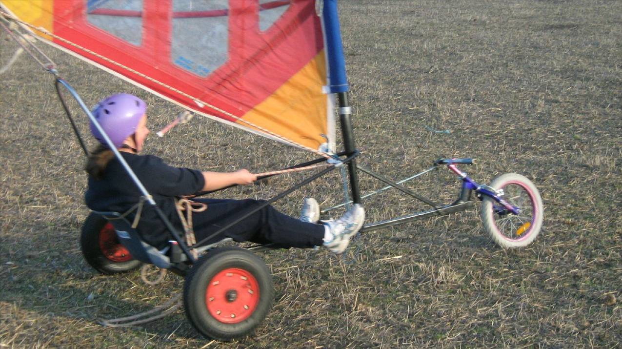
the steering has proven to be very satisfactory...precise and not at all twitchy at speed.
The "Mad.Project's " system has much more rake and I'm pretty sure a rose joint would not be able to flex enough. I've been playing with bits of the hydraulic pipe...I think it will be the go![]()
![]()
![]()
Just have to talk Bodie's dad into letting us have some offcuts![]()
![]()


