I want to insert a relay into my fridge fan (which is a water pump) circuit.
I just cannot work out how to get it sorted!!
Power goes into the fridge controller thru the Lg +ve (2nd from top) & I think, out via the Sm +ve (3rd from top) when turned on via the thermostat with F being, presumably, the switch.
Do I run relay 87 to Pump +ve with the Pump -ve running to F on the controller with the Sm +ve to 85?
TIA I am completely lost here!!

Select to expand quoteLazzz said..
I want to insert a relay into my fridge fan (which is a water pump) circuit.
I just cannot work out how to get it sorted!!
Power goes into the fridge controller thru the Lg +ve (2nd from top) & I think, out via the Sm +ve (3rd from top) when turned on via the thermostat with F being, presumably, the switch.
Do I run relay 87 to Pump +ve with the Pump -ve running to F on the controller with the Sm +ve to 85?
TIA I am completely lost here!!
Hi, if it were me I would piggyback #86 to the pos connection of the fan on the unit, #85 to the neg bus bar along with the water pump neg, #30 to the pos bus bar, fused of course and #87 to the water pump pos. That way the load is straight from the distribution panel with only one connection to the fridge unit drawing very little current.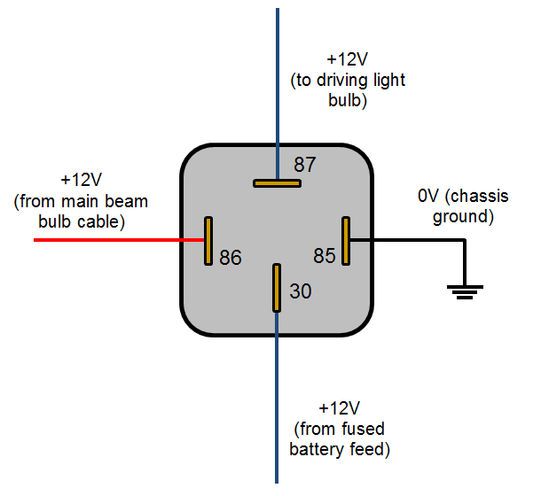
Hi Lazz
A couple of questions.
Do you want the water pump to cycle with the fan in your drawing?
Is that fan an internal fan inside the refrigerated box?
Does the fan cycle on/off with the thermostat?
Is the water pump to circulate water through a water cooled condenser?
C,P,T. I am guessing C is compressor, T is thermostat, and P is power (although I would have expected a + )
The "mainbeam " switch and the "over ride " switch in your diagram make it a little difficult .
Also so there is a discrepancy between your diagram and Uncle Bob's which adds confusion.
Yours diagram has and the active for the relay coil and for the negative whereas Bob's is opposite.
In reality it can be wired either way.
My guess is all of your ? negatives are fine as shown in the diagram.
And the positive feed to 30 is correct.
I would attach your 85 to the second + down form the top. The one above F.
Or attach it (85) to C on the thermostat circuit . That is if my guess that C is Compressor is correct.
If you have some, just connect the wire form 85 with an alligator clip. If is correct, solder all connections.
Don't use slide on spade connectors.
Gary
Thanks for your help, I got it sorted :)
Yep, the numbers 85 & 86 are back to front in my diagram - I just pulled a relay pic from google!!
I ended up going with: 86 (corrected) to Sm +ve & 85 to F with the rest per my diag; 87 to pump etc.
Works like a charm.Select to expand quotegarymalmgren said..
Hi Lazz
A couple of questions.
Do you want the water pump to cycle with the fan in your drawing? YES
Is that fan an internal fan inside the refrigerated box? NO
Does the fan cycle on/off with the thermostat? YES with a delay
Is the water pump to circulate water through a water cooled condenser? YES
C,P,T. I am guessing C is compressor YES, T is thermostat YES, and P is power NO (although I would have expected a + YES 3rd from top)
The "mainbeam " switch and the "over ride " switch in your diagram make it a little difficult . Yeah, bad google pic :(
Also so there is a discrepancy between your diagram and Uncle Bob's which adds confusion. Bobs is correct
Yours diagram has and the active for the relay coil and for the negative whereas Bob's is opposite.
In reality it can be wired either way.
My guess is all of your ? negatives are fine as shown in the diagram.
And the positive feed to 30 is correct.
I would attach your 85 to the second + down form the top. The one above F.
Or attach it (85) to C on the thermostat circuit . That is if my guess that C is Compressor is correct. I used to have it like this but needed the delay
If you have some, just connect the wire form 85 with an alligator clip. If is correct, solder all connections.
Don't use slide on spade connectors.
Gary
Lazzz, is the pump for a water cooled condenser? If so the diagram you have drawn is not really good and not very power efficient. By adding a water cooled condenser it will improve your refrigeration of sight but you don't need to run the air cooled condenser at the same time as the water cooled condenser and it only needs to run when the compressor is running. If you install a HP control you can run on water and if anything goes wrong eg a water blockage, it will switch over to air cooled. You would have a selector switch to select air or water or auto. The installation of a small circulation fan that runs continuously in the fridge / freezer will also improve things out of sight. Let me know if you want any diagrams.
John
Strange because F in the diagram is the negative for the fan. Maybe you have just run it in series,
It does cycle off with the fan doesn't it?
gary
Select to expand quotegarymalmgren said..
Strange because F in the diagram is the negative for the fan. Maybe you have just run it in series,
It does cycle off with the fan doesn't it?
gary
Hi Gary I have seen a quite a few fridge systems switched in the negative , must be a fridge thing.![]()
Thanks heaps for your input fellas :)
Yes Gary, F is the negative switch. D is the fault LED - 1 flash = battery protection cut-out; 2 flashes = fan (pump) over-current cut-out; etc.
John, I am only running water cooled, no fan. I have two small circulation fans in the fridge that I only run when I am on the boat - I might start leaving one now on though. I used to run sea water but now just circulate my fresh water.
I have a completely separate 240V air cooled system - I don't use this much cause I am on a swing mooring!!
Pic is before the 12v BD50 was connected.
I previously had the pump wired to the "C" (compressor) terminal but now using the "F" terminal there is a slight delay & with the relay it doesn't matter how much the pump draws. I also get a fault code if the pump circuit has a problem - before it would just show as a battery protection cut-out.
This is the new (not very pretty) wiring:


Select to expand quoteJode5 said..
If you install a HP control you can run on water and if anything goes wrong eg a water blockage, it will switch over to air cooled. You would have a selector switch to select air or water or auto.
John
You do have me thinking about this now though!!! :)