I receive the equipe trading (select) newsletter, thought I'd share their stuff about fins (It's way over my head but some might find it interesting) ![]()
THE SCIENCE OF WINDSURFING FINS
Since you love windsurfing as much as us we thought you might appreciate some insight and theory into fin dynamics. There's a lot of hype and jargon spoken about fins, so we hope you find this theoretical information useful when making choices about what fins to buy.
There's a lot to cover, so we're going to send this to you in a series of short episodes, starting with a common misconception … THINNER PROFILES ARE FASTER
Indeed thinner profiles are faster - BUT only when used for speed sailing at very high speeds. For 'normal' speeds, thinner profiles in most constructions simply don't deliver enough LIFT. There are a lot of influences on generating lift: Surface area, profile (thickness)Profile form (wing shape or camber - the shape of the fin in plan shape or cross section if you like), Chord (the front-to-back width)Depth top to bottomProfile ratio (chord length in mm. ÷ thickness in mm. expressed as %)StiffnessFlexTwist … and more, that all play their part.
Any one fin that's built without taking into account fine tuning of all of the above for specific purpose is selling you short in control, speed and lift.

Both the profile form and profile ratio are normally optimized for the use and intended speed range. A higher % profile will, in principle, generate more lift compared to a lower % profile at a given speed - but with a higher resistance. For speed, the amount of lift generated should be high, while the resistance must be as low as possible. Profile efficiency (lift ÷ drag ratio) has a relation to the required speed range and type of profile. Profile forms and outlines are a real scientific area. E.g., the realms of NASA, Boeing, Airbus, Shipbuilders etc. who, for as long as aerodynamics has existed, have spent infinite amounts of money to find 'the ideal profile'.

At higher speeds thinner profiles normally show a higher efficiency. Hence thinner profiles are better suited at higher speeds - but not necessarily for reaching them. There's a cut-off point at around 9% (of chord ÷ thickness). Below 9% would typically be used for speed. 9% or higher for slalom use. It could be a good idea to develop fins with >12% ratios specifically for very low speeds, like first time use etc . The result will be a high-lift fin at very low speed. Ideal to learn windsurfing on … The amount of lift generated by a fin depends on a number of variables. If speed doubles, lift will increase by a factor of 4!Angle of attack (lift increases linearly with the angle).Profile form and ratio (the higher the ratio the more lift per a given area).Rake angle also influences the lift figure considerably (a weed fin with 45-deg. delivers considerably less lift compared to a slalom fin with 12 deg.
SPECIAL SAUCE
Welcome back to episode 2 of our series on windsuring fins - where we're busting a few myths and giving you the facts on fin technology.
Last time we got really scientific. This time we're going to use that theory and examine a few more preconceptions.
YES OR NO - THE MORE SURFACE AREA MY FIN HAS THE MORE LIFT IT WILL GENERATE
Maybe yes - but only when all other parameters like twist / flex / rake angle and profile are the same. These parameters all influence the amount of lift a fin generates. It's easy to construct fins with equal amounts of lift - but that differ 30% in surface area. As explained in episode 1, using a thin (e.g., 8%) profile ratio compared to a thick (e.g., 11%) profile ratio, the amount of lift per given area differs by a fair amount.

FACT OR FICTION? SHORTER FINS ARE ALWAYS FASTER THAN LONGER FINS
A real misconception! So … for a given board type and sail size AND the type of sailing (e.g., speed or upwind sailing) only one size of fin will give the optimal amount of lift. If your fin's too short it won't lift the board enough and therefore you'll have more wetted surface area and be significantly slower than if you used a longer fin
If your fin's too long it'll deliver too much lift and as a result your board will be difficult to control with errative behaviour such as spontaneous tail walks. Next time we'll look at profile, how construction methods influence handling characteristics and price factors such as custom fins versus production models.
Love to hear Slowies , Mal and Wolfgang's thoughts on this theory. Generally NAACA foils are good for water even thou they were designed for air and much higher speeds.
I'm still struggling with the concept of lift and what it actually is. So far, I'v understood it to be the fin's ability to resist cavitation, with the the effect being that a high lift fin gives you the ability to aggressively angle the board in comparison to it's current direction in order to steer in a different direction effectively without the fin 'letting go' through cavitation.
Some of the references to lift in the above article make me question whether I've really comprehended this basic concept....ie a high lift fin reducing wetted surface area???
Eckers..
Wow!
This is exactly what i got from Tribal (Lockwood) after subscribing last week.
Select to expand quoteeckas said..
Some of the references to lift in the above article make me question whether I've really comprehended this basic concept....ie a high lift fin reducing wetted surface area???
Eckers..
The article is not clearly written. "Lift" generally refers to the component of force developed by a foil in the direction normal to the long axis of the foil and the direction of travel. ( The component in the other direction is called drag). Which for a windsurfer is sideways. Unless your fin flexes a lot, or you can't keep the board flat, in which case a little bit of this lift is upwards in a direction which might tend to "lift" the board out of the water.
He's possibly referring to the "wetted surface area " of the board? If your fin is too small you have to use a bit of the hull for lift. ie. Going up wind wave board style, tilting to windward with a rail stuck in
Eckas, when you are powered up and planing, your board is not level (longitudinally or along it's length). ie you are dipping one rail of your board below the other to create resistance to sideways slip (added to the slip resistance provided by the fin). Now because this tilts the board over it also tilts the fin sideways. Now if you have the nose of the board pointed in the air (higher than the tail of the board) your fin now has an angle of attack relative to the water flow and this creates lift as the fin is effectively a foil. The vertical component of this lift pushes the board up out of the water which reduces the amount of board in the water (wetted area) and lowers your drag which makes you go faster as you are now more efficient. If it helps, slot a credit card or a post it down between your fingers as the fin and your hand is now the board, move it around to see what effect board orientation has on fin orientation.
I also think people make many 'generalised' statements about fin size like bigger sail = bigger fin, what is the definition of 'bigger' is it more area? Is it more length? Is it any combination of the two to give more lift?
How much does a fin actually flex when you are planing along? Does the sideways component of lift get cancelled by the opposite sideways component resisting slip?
BTW: awesome post Hoges, it's food for thought
Select to expand quoteBSN101 said..
Wow!
This is exactly what i got from Tribal (Lockwood) after subscribing last week.
Maybe part of/affiliated to the group ? Equipe own Lofts sails/Attitude sails/Select/Bic sport/Unifiber and Bern
Just when l thought l was educated on fins this comes along!
Interesting read too.
At what part of the fin is the profile ratio measured ?.
Yes, a very interesting post Sean.
certainly agree about less lift with weed fins ....they take a bit of getting use to ..don't like em but you have to have them over west.
Select to expand quotejn1 said..
At what part of the fin is the profile ratio measured ?.
Yes, a very interesting post Sean.
Do you mean the thickness to chord ratio? I make my fins so that it's constant over the length of the fin, as the fin narrows it also gets correspondingly thinner.
If you mean taper ratio thats the difference between the base width and the tip width.
I believed this for a long time, until yoyo put me right.Select to expand quote
A higher % profile will, in principle, generate more lift compared to a lower % profile at a given speed
And for asymmetric foils it's true, but for symmetrical foils, it's not exactly true.
For symmetrical foils lift is Dependant on foil area, velocity and angle of attack only.
The thing with thicker foils they can run at higher angles of attack so are capable of higher lift
Select to expand quotedecrepit said..
Yes, the thickness to chord ratio. Is it practice to keep this ratio constant, or do fin makers vary this ratio at different points (c/4 line) on the fin ?

I've absolutely no idea of what's going on here, so I stick to the same ratio all the way up.
I really don't like doing something I don't understand.
I assume ventilation is likely to start from the base, whereas the tip is more insulated from the atmosphere. So it makes sense to have a foil shape that has a higher stall angle at the base, and a faster foil shape away from the atmosphere.
But I'm only guessing here!
Would the very thin tip reduce the pressure differential (top to bottom) and help prevent vortices and therefore drag at the tip? ie are the issues with aerofoils similar to a fin in water?
Select to expand quotePaddles B'mere said..
Would the very thin tip reduce the pressure differential (top to bottom) and help prevent vortices and therefore drag at the tip? ie are the issues with aerofoils similar to a fin in water?
I believe you have something there, perhaps there are now 2 good reasons for thinning the fin towards the tip, next time I'm playing in the shed I'll give it a go.
The issues are basically similar, except for us we have another much less dense medium within centimeters of the fin, so there are ventilation issues, and at high speeds cavitation can also become a problem. Things a wing in the atmosphere doesn't have to worry about.
Select to expand quotePaddles B'mere said..
Would the very thin tip reduce the pressure differential (top to bottom) and help prevent vortices and therefore drag at the tip? ie are the issues with aerofoils similar to a fin in water?
Yep,
If the profile remains the same along the span then the theory is an elliptical plan form is required to maintain a constant span wise angle of attack otherwise it would increase at the tips... So yes the profile needs to varied in some way along its span.
Attached is a bit of light reading, if you find this stuff fascinating... ![]() web.stanford.edu/~cantwell/AA200_Course_Material/AA200_Course_Notes/AA200_Ch_12_Wings_of_Finite_Span_Cantwell.pdf
web.stanford.edu/~cantwell/AA200_Course_Material/AA200_Course_Notes/AA200_Ch_12_Wings_of_Finite_Span_Cantwell.pdf
Similar reasons for sail twist as well...
Select to expand quoteracerX said..
>>>>
Attached is a bit of light reading, if you find this stuff fascinating... ![]() web.stanford.edu/~cantwell/AA200_Course_Material/AA200_Course_Notes/AA200_Ch_12_Wings_of_Finite_Span_Cantwell.pdf
web.stanford.edu/~cantwell/AA200_Course_Material/AA200_Course_Notes/AA200_Ch_12_Wings_of_Finite_Span_Cantwell.pdf
Similar reasons for sail twist as well...
As I said earlier, I haven't got a clue! much too much maths in there for me. Presumably you need to calculate the optimum decrease in thickness taking into account profile shape/rake, angle of attack and speed.
How good will it be to just guess???? Not enough change is probably better than none at all. But overdoing it wouldn't be good either.
The state of the art in fin designs is way past the guesswork stage with quite sophisticated cfd used along with optimisation searches. But good designs are still possible based on some basic principles. Understanding a few basic principles can help.
increasing thickness ratio improves clmax up to a peak that varies with re but generally starts to reduce after about 13 to 15% t/c. higher re generally increases the t/c for clmax and increases clmax.
sweep increases the cl at the tip. Taper increases cl at the tip. The tip operates at lower re so generally a thinner tip section will give a slightly higher clmax. Sweep also results in fin twist which reduces the tip cl.
thickness of the fin has a big effect on bending stiffness so a g10 fin may need to be thicker than its carbon sister to have similar bending stiffness.
a good book for foil sections is abbot and von doenhoff "theorey of wing sections". However modern foil designs use different methods. Eppler developed a program for pc's and paved the way for desktop foil design. Mark drela developed xfoil which is fairly widely used. Java foil is another. More sophisticated designs now use euler methods and even navier stokes or boltzmann particle methods. Some very good 3d analysis tools are available now. Vs aero has been around for a while and solid works has a nice cfd package. X flow allows really sophisticated analysis, including the free surface with waves, but it needs a lot of processing power.
or you can go out to the shed and just carve something, either way its fun.
Interesting read and discussion. One possible reason to thin the tips is more flex near the tip for more lift.
Weed fins are funny. The one kind a local slalom guy likes best has a lot of flex near the tip. Deltas have the least flex of them all. With the BP Delta, it's extreme; you really need to push in the leeward rail to get any lift out of it. Took me a while to get used to, but I like it now. It's not a speed fin, though, the MUF Deltas seem to be better for speed. I think they could benefit from a cutout similar to the BP Delta, though.
so, what is the "logic"/physics behind the Lessacher weed fins ??
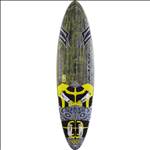
and Makani are making strange leading edge - or has the fin shape been flipped and that is the trailing edge ??? ![]()
either way - what the hay ??

Select to expand quotePiv said..
or you can go out to the shed and just carve something,
A lot of sailors go pretty well doing just that. But I've no doubt that the CFD devices can split hairs on the best shapes. In reality all fins will have an optimum angle of attack for best lift to drag. But we don't get to choose that angle of attack on the water. We adjust the angle of attack to give the required lift. So to be using the optimum angle of attack on the water you just have to be lucky and have the right sized fin on board for the particular speed and lift combination you need at that instant.
So the question is. How sharp is the drop off on the lift- to- drag graph as you move away from optimum angle of attack? Compared to... How fast does the lift to drag fall off as you move the foil shape a little away from the ideal shape as predicted by the CFD calculations? ( Or The partial derivative of lift to drag with respect to shape vs. the partial derivative of lift to drag with respect to angle of attack if you like. )
And do these CFD calculations assume uniform flow? Unless you're on the perfect speed course the turbulence in the water is going to put all sorts of unknowns into the equation. If you're on the perfect speed course the tip of your fin is so close to the bottom any modelling of tip vortices, elliptical plan shapes, is a a bit pointless.
I don't know exactly what goes on in these fin modelling exercises but I think the fact that sailors get out there with fins moulded by eye in the back shed and do quite well says something.
Select to expand quotePiv said..
>>>
or you can go out to the shed and just carve something, either way its fun.
Thanks Piv, that's what I've been doing, and it seems to work, it's too late in the day for me to do a quick maths course. So I guess I'll just carry on, but try thinning the tips a little and see what happens.
Select to expand quotePiv said..
The state of the art in fin designs is way past the guesswork stage with quite sophisticated cfd used along with optimisation searches. But good designs are still possible based on some basic principles. Understanding a few basic principles can help.
increasing thickness ratio improves clmax up to a peak that varies with re but generally starts to reduce after about 13 to 15% t/c. higher re generally increases the t/c for clmax and increases clmax.
sweep increases the cl at the tip. Taper increases cl at the tip. The tip operates at lower re so generally a thinner tip section will give a slightly higher clmax. Sweep also results in fin twist which reduces the tip cl.
thickness of the fin has a big effect on bending stiffness so a g10 fin may need to be thicker than its carbon sister to have similar bending stiffness.
a good book for foil sections is abbot and von doenhoff "theorey of wing sections". However modern foil designs use different methods. Eppler developed a program for pc's and paved the way for desktop foil design. Mark drela developed xfoil which is fairly widely used. Java foil is another. More sophisticated designs now use euler methods and even navier stokes or boltzmann particle methods. Some very good 3d analysis tools are available now. Vs aero has been around for a while and solid works has a nice cfd package. X flow allows really sophisticated analysis, including the free surface with waves, but it needs a lot of processing power.
or you can go out to the shed and just carve something, either way its fun.
Thanks mate, but can you include a glossary for the abbreviations please? ![]()
Mal Wright did a lot of work with CFD modelling fin performance for speed fins in particular. He introduced me to a concept he called the 'drag bucket'. As i roughly understand it, this is the point where the angle of attack of the fin approaches it's optimum for maximum lift to drag ratio. (somewhere near to top range of the designed speed)
The practical side of it is that some of his proto. fins had extremely favourable L/D ratio at top speeds, but getting them to 'drop into the bucket' was often problematic.
I think the TM45 V6 was a good example of this. On the few occasions I managed to get it 'switched on' or 'in the bucket', it took of like I was on ice. But all sorts of things had to be perfect before I could achieve that point. The 'drop in' point was somewhere around 41-42 knots for me. The V7/V8 were designed to 'drop in' a whole lot easier and proved faster because of that, even though in theory they was not quite as efficient at the ultimate top end. I have never had any trouble getting the TM48 fins 'switched on', and that fin is much better suited to my size. ![]()
Interestingly, Mal was convinced that on some days the 'water was slow' at Sandy Point. What he meant by this was that there was some sort of turbulence in the water and surface chop, most likely from tidal influences, that made it much harder to get the fins to 'drop in'. Some days, it was definitely noticeable that we were slower when everything else seemed to indicate we should be faster.
Edit: All the above mentioned fins are asymmetric speed fins between 20 and 22cm deep.
Some of his explanations and graphs are still up here: http://www.intellimass.com/TimeMachine/index.htm
Another Edit addition from the above link:
Mal. Quote: ".......My results were good today but I did notice that the fin did not have the free-revving feeling that it displayed on the east bank. I put this down to the chop and disturbed water while I was sailing. Every now and then I managed to get a little acceleration that showed what was possible but it never lasted for more than a second. As the tide dropped very late in the day the fin started to perform a little better, and I am confident that if I had been able to sail during the low tide, the results might have been quite a bit different. Only time will tell."
Select to expand quotejoe windsurf said..
so, what is the "logic"/physics behind the Lessacher weed fins ??
I'm yet to be convinced that either of those apply, even though some people swear by them.Select to expand quote
and Makani are making strange leading edge - or has the fin shape been flipped and that is the trailing edge ???
either way - what the hay ??
This looks to be inspired by the "turbulators" on whale fins, apparently enables them to work at very large angles of attack so gain maneuverability. I'm not sure what it's meant to do on a wave fin. Certainly wouldn't want any weed or cray pot ropes around!
Just installed the cli version of xfoil, think I may just get the hang of it while I can still windsurf.
That's better I just installed the gui xflr5. I think I'll get the hang of that a bit quicker.